Maker workflow · 10 min read
Prepare an Image Relief for CNC Carving or 3D Printing
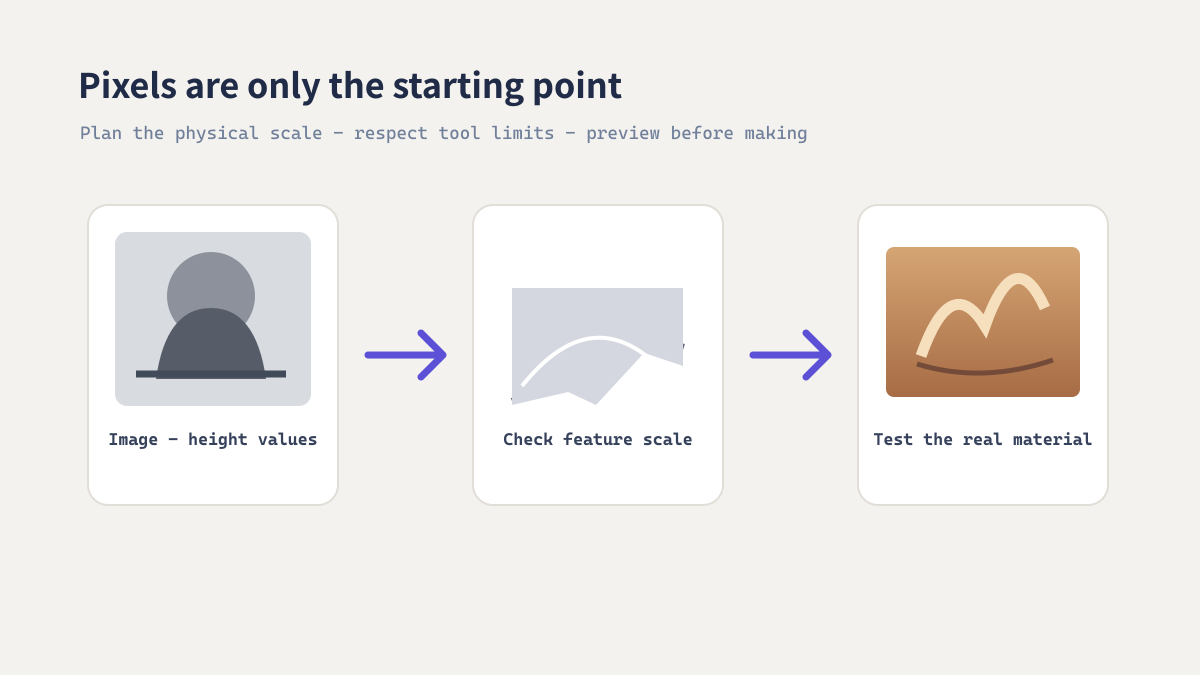
A grayscale image can become the starting surface for a carved plaque or printed relief, but pixels do not automatically translate into manufacturable depth. Subject readability, material scale, tool or nozzle limits, and a test preview all belong in the workflow.
Choose an image that can become a relief
Prioritize silhouette and tonal separation
A clear subject against a simple background is easier to read as a shallow relief than a busy photograph with overlapping edges. Strong cast shadows can be mistaken for physical depth, so prefer even lighting and inspect whether the important shapes remain recognizable in grayscale.
AI depth estimation can create a useful starting map from a photo, but occlusion, reflections, hair, and transparent objects may need manual cleanup. Keep the result as an editable intermediate rather than treating it as a finished toolpath or mesh.
Prepare the depth range for a physical object
Match the map to the intended scale
A small screen texture can disappear when machined with a large cutter or printed with a wide nozzle. Physical limits should guide the map's detail, not only the source image resolution.
- Choose the final plaque width, height, and maximum relief depth before editing the map.
- Generate a height-map candidate with ImageTool.cc and inspect the broad forms first.
- Adjust contrast and smoothing to separate the subject without creating noisy micro-detail.
- Import the map into the target 3D or CAM workflow and confirm which value represents the top surface.
- Set a conservative physical depth and preview the mesh or toolpath at the intended size.
- Test a small section or sample before committing to the full material or print.
Real example: a shallow portrait plaque
Simplify before increasing depth
For a portrait plaque, select a front-facing photo with a readable outline, generate several depth candidates, and choose the one that preserves the nose, eyes, and outer silhouette without exaggerated shadows. Flatten the back and add a border in the 3D application; then check the preview from the expected viewing distance.
Manufacturing checks before export
A height map is not a fabrication guarantee
- Check minimum feature size against cutter diameter or printer resolution.
- Confirm the CAM or slicer interprets black and white in the intended direction.
- Inspect steep walls, thin islands, and the back-face thickness.
- Use a test cut or small print to validate the selected depth range.
- Follow the machine, material, and software maker's safety and setup guidance.